Product Description
Product Description
| Product Name | Small 1/8 Inch 3.2mm Hose Barb Valved Fluid Quick Connect Tube Fitting Shut Off Quick Disconnect Coupling |
| Technology | Injection Molding |
| Usage | Standard flow quick-disconnect couplings require a body and an insert in the same flow size. Plug insert into body to connect fitting and easily disconnect the fitting by simply press the thumb latch. |
| Application | medical devices, laboratory, life science, biopharmaceutical, biochemical analysis, bioengineering, circulating water cooling pipe system, water treatment and disinfection, food&beverage, packaging machinery, industrial and hundreds of other applications; |
| Adapted Medium | Gas/Liquid |
| Material | POM Plastic |
| Seal Ring Material | Buna-N/FKM/EPDM/Silicone rubber, depend on your usage |
| Valve Spring | 316 Stainless Steel |
| Temperature Range | 32°F – 180°F (0°C – 82°C) |
| Pressure Range | Vacuum to 100 psi, 6.9bar |
| Valve Option | Valved(shut off) or Non-valved (straight through) |
| Shape Option | Panel Mount/In-line/Elbow/NPT Threaded; |
| Hose Barb Size | 1/16″ =1.6mm (01); 1/8″= 3.2mm (02); 3/16″= 4.8mm (03);
1/4″=6.4mm (04); 5/16″=8mm (05); 3/8″=9.6mm (06); |
| Threaded End | 1/8″-27NPT, 1/4″-18NPT Male Thread |
1/4″ Flow rate, 1/8″(3.2mm) Hose Barb Valved Coupling Body&Insert
Related Products You May Like
1/4″ Flow Rate All Plastic Series Couplings
1/8″ Flow Rate Medium Series Couplings
1/16″ Flow Rate Small Series Couplings
FAQ
Q1: Are you trading company or manufacturer?
A1: We are 15 years factory. Welcome to visit our factory.
Q2:What is your sample policy?
A2:
1. Only for terminal manufacturer;
2. Please kindly provide detail information of company for sample application process. Sample is available after confirmed and approved by management;
3.The international freight cost should be paid by the applicant;
Q3:What is your terms of payment?
A3: 100% payment before delivery; T/T 50% as deposit when mass customization, the balance before shipment.
Q4: How about your delivery time?
A4: Generally, it will take about 7-15 days after payment confirmed. The specific delivery time depends on the items and the ordered quantity .
Q5:What’s the shipping way?
A5: Usually by DHL, UPS, TNT, FedEx express or as your request.
Q6: Can you produce according to the samples?
A6: Yes, we can produce by your samples or technical drawings. We accept ODM & OEM.
Packaging & Shipping
Company Profile
Our company has specialized in researchs and developments, designs, manufactures, promotes and sales of a variety of plastic fittings, plastic connectors,quick disconnect couplings, check valves, filters, CHINAMFG pumps, solenoid valves,plastic tubings and other accessories applied in fluid systems. Our products are widely used in all kinds of products, machinery,devices and process of liquid and gas pipe system, In the life sciences and special industrial markets have thousands of applications to be used, Such as blood pressure, blood oxygen monitoring module and blood gas recovery equipment, biochemical analysis/inspection equipment, dialysis water treatment equipment, treatment and reuse equipment, breathing anesthesia, incubator, bioengineering and circulating water cooling pipe system, solvent printer, inkjet printer,film printer and ink supply system, water quality online analytical instruments, laboratory equipment, food machinery, fermentation system process equipment, plating equipment, PCB&LCD process equipment, chemical equipment, packaging machinery, water treatment and disinfection equipment, inflatable products, automation equipment…And so on.
Depending on the 15-years experience in various fluidic control systems, our company has had a set of comprehensive manufacturing systems involving in R&D and design, mold manufacture, plastic injection, assembly & inspection, finished-product sales and warehousing logistics. It has many advantages of stable quality, efficient production and punctual delivery, which can be said a trustworthy partner.
Following different requirements from wider customers, including drawings or samples offering, our company can offer satisfied design services and mass customized services.
We’re looking forwards to cooperating with a wide range of OEMs and ODMs.
/* January 22, 2571 19:08:37 */!function(){function s(e,r){var a,o={};try{e&&e.split(“,”).forEach(function(e,t){e&&(a=e.match(/(.*?):(.*)$/))&&1

Handling Overloads and Stall Conditions in Fluid Couplings
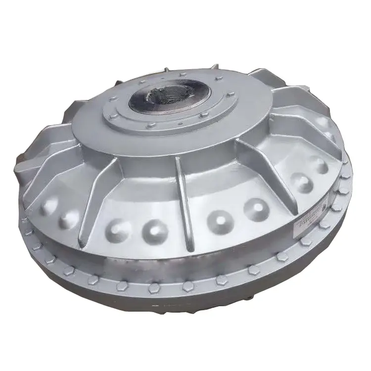
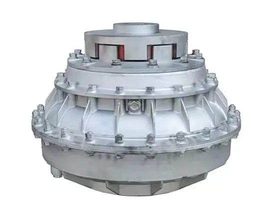
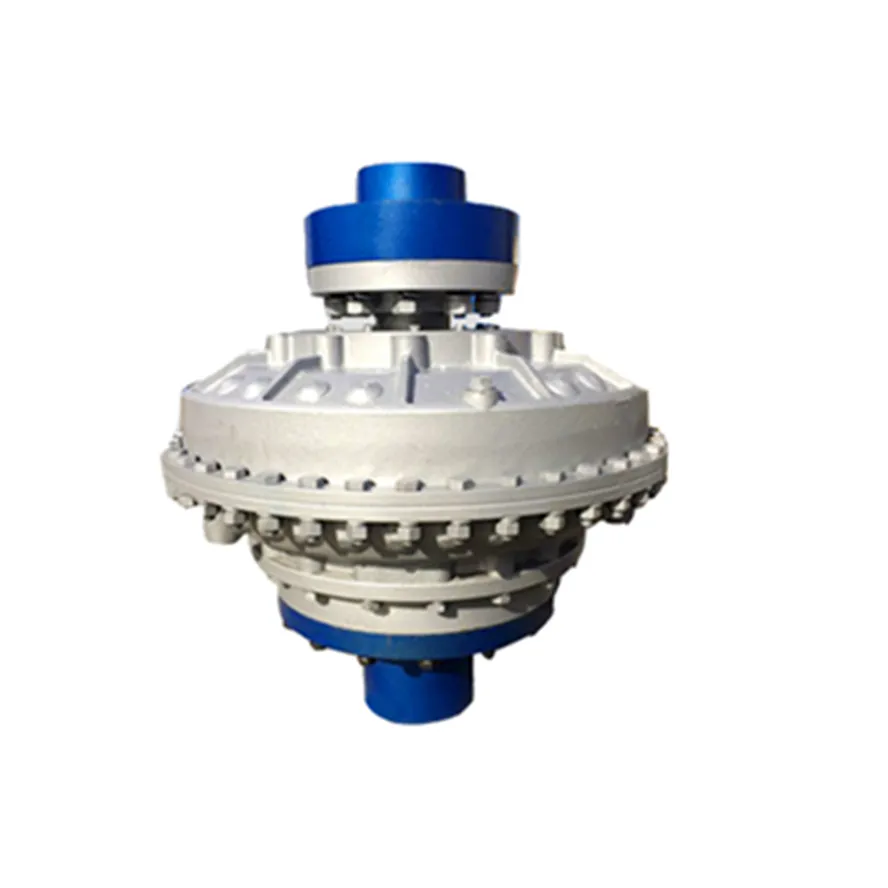
A fluid coupling is designed to handle overloads and stall conditions in power transmission systems. When an overload or stall occurs, the fluid coupling utilizes its unique operating principle to protect the drivetrain and the connected machinery:
- Slip Feature: One of the key characteristics of a fluid coupling is its ability to slip at high torque loads. When an overload situation arises, the fluid coupling allows some relative motion between the input and output sides, known as slip. This slip absorbs the excess torque and prevents it from being transferred to the driven equipment, effectively protecting it from damage.
- Fluid Circulation: During normal operation, the fluid inside the coupling circulates smoothly between the impeller and turbine, transmitting torque with minimal losses. However, when an overload or stall condition occurs, the fluid circulation may become turbulent, generating heat in the process. This heat dissipation helps in absorbing and dissipating the excess energy, preventing the transmission system from experiencing sudden stress.
- Automatic Reconnection: After an overload or stall condition, once the excess torque is dissipated through slip and heat, the fluid coupling automatically reconnects the input and output sides, resuming the power transmission. This automatic reconnection ensures that the system returns to normal operation once the overload situation is resolved.
- Sturdy Construction: Fluid couplings are designed with robust and durable materials to withstand high torque and thermal stresses during overload conditions. The strong construction ensures that the fluid coupling remains reliable and operational even after multiple overload events.
Overall, a fluid coupling’s ability to handle overloads and stall conditions makes it a reliable and essential component in various industrial applications. By providing overload protection and slip characteristics, fluid couplings help prevent costly damage to equipment, increase operational safety, and contribute to the longevity of the entire power transmission system.

Real-World Case Studies: Improved Performance with Fluid Couplings
Fluid couplings have been widely adopted in various industries, and numerous real-world case studies demonstrate their positive impact on performance and efficiency. Here are a few examples:
Case Study 1: Mining Conveyor System
In a large mining operation, a conveyor system used to transport heavy loads of ore experienced frequent starts and stops due to fluctuating material supply. The abrupt starting and stopping led to significant wear and tear on the conveyor components, causing frequent breakdowns and maintenance downtime.
After installing fluid couplings at critical points in the conveyor system, the soft start and stop capability of the fluid couplings significantly reduced the mechanical stress during operation. This led to a smoother material flow, reduced conveyor wear, and extended equipment life. Additionally, the fluid couplings’ overload protection feature prevented damage to the conveyor during peak loads, ensuring uninterrupted production.
Case Study 2: Marine Propulsion System
In a marine vessel equipped with traditional direct drive systems, the crew faced challenges in maneuvering the ship efficiently. The fixed propeller arrangement made it challenging to control the vessel’s speed and direction accurately, leading to increased fuel consumption and decreased maneuverability.
By retrofitting the vessel’s propulsion system with fluid couplings, the ship’s performance improved significantly. The fluid couplings allowed for flexible and smooth speed control, enabling precise maneuvering and reduced fuel consumption. The ability to adjust the load on the propeller enhanced the vessel’s overall efficiency, resulting in reduced operating costs and improved environmental sustainability.
Case Study 3: Industrial Pumping Station
In an industrial pumping station, the constant starting and stopping of the pumps caused water hammer and pressure surges within the pipeline network. The sudden hydraulic shocks led to pipe bursts, valve failures, and increased energy consumption.
After implementing fluid couplings in the pump drive systems, the pumps could be softly started and stopped. The fluid couplings’ torque control capabilities ensured a gradual increase in pump speed, eliminating water hammer and pressure surges. As a result, the pumping station’s reliability improved, maintenance costs decreased, and the energy consumption reduced due to smoother pump operations.
These case studies demonstrate the positive effects of using fluid couplings in various applications. They highlight how fluid couplings contribute to improved performance, reduced mechanical stress, enhanced control, and cost savings in industrial machinery and systems.
“`
Principle of Hydrodynamic Fluid Coupling
A hydrodynamic fluid coupling operates on the principle of hydrokinetics, utilizing hydraulic fluid to transmit power between an engine or prime mover and a driven load. The key components of a fluid coupling are the impeller, the turbine, and the housing filled with hydraulic fluid.
Here’s how the principle works:
- Impeller: The impeller is connected to the engine’s crankshaft and is responsible for driving the hydraulic fluid. As the impeller rotates, it creates a flow of fluid within the housing.
- Fluid Flow: The rotational motion of the impeller causes the fluid to move radially outward, towards the housing walls. This generates a high-velocity fluid flow in the housing.
- Turbine: The turbine is connected to the driven load, such as a transmission or machinery input shaft. As the fluid flows onto the blades of the turbine, it causes the turbine to rotate.
- Power Transmission: The kinetic energy of the high-velocity fluid is transferred to the turbine, resulting in the rotation of the driven load. The power transmission is achieved purely through the hydrodynamic effect of the fluid flow.
- Slip: In a fluid coupling, there is always a slight difference in speed (slip) between the impeller and the turbine. This slip is necessary to allow the fluid to accelerate from rest to the speed of the turbine. As a result, the output speed of the driven load is always slightly less than the input speed from the engine.
Hydrodynamic fluid couplings provide several advantages, such as smooth power transmission, overload protection, and torsional vibration dampening. However, they do not provide torque multiplication like torque converters do, making them more suitable for applications where precise speed matching is required.


editor by CX 2024-05-10
by
Tags:
Leave a Reply