Product Description
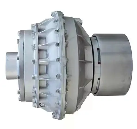
Diaphragm Coupling Shaft Coupling (JMI)
JM Series Diaphragm Coupling of flexible metal flexible coupling, which rely on the metal diaphragm to transmit torque from the main connection, motivation, has the advantages of elastic damping and no lubrication, no noise, is an ideal product for replacing the gear coupling and coupling current. It can compensate the axial, radial and angular deviation caused by the manufacturing error, installation error, bearing deformation and the change of temperature rise.
The main characteristics of JM Series Diaphragm Coupling:
1.Compensation 2 axis misalignment of the ability, and tooth type coupling can be much more than a double angle displacement, radial displacement of the small, flexible, allowing a certain axial, radial and angular displacement.
2. Obvious damping effect, no noise, no wear and tear.
3.High transmission efficiency, up to 99.86%. Especially suitable for medium and high speed high power transmission.
4.Adapt to high temperature (-80+300) and harsh environment, and can be in shock, vibration, safety and dynamic conditions.
5.Simple structure, light weight, small size, convenient assembly and disassembly. Without moving the machine can be disassembled (with intermediate type), no need of lubrication.
6.Accurately convey the rotational speed, the operation has not turned bad, can be used for the transmission of precision machinery.
JM series diaphragm flexible coupling is widely used in machinery and equipment industry, metallurgy, mines, petroleum, chemical, electric power, shipbuilding, lifting transport, textile, light industry, agricultural machinery, printing machinery and water pump, fan, etc. in the transmission of power machine.
|
||||||||||||||||||||||||||||||||||||||||||||||||||||||||||||||||||||||||||||||||||||||||||||||||||||||||||||||||||||||||||||||||||||||||||||||||||||||||||||||||||||||||||||||||||||||||||||||||||||||||||||||||||||||||||||||||||||||||||||||||||||||||||||||||||||||||||||||||||||||||||||||||||||||||||||||||||||||||||||||||||||||||||||||||||||||||||||||||||||||||||||||||||||||||
Detailed Photos
Company Profile
HangZhou CHINAMFG Machinery Manufacturing Co., Ltd. is a high-tech enterprise specializing in the design and manufacture of various types of coupling. There are 86 employees in our company, including 2 senior engineers and no fewer than 20 mechanical design and manufacture, heat treatment, welding, and other professionals.
Advanced and reasonable process, complete detection means. Our company actively introduces foreign advanced technology and equipment, on the basis of the condition, we make full use of the advantage and do more research and innovation. Strict to high quality and operate strictly in accordance with the ISO9000 quality certification system standard mode.
Our company supplies different kinds of products. High quality and reasonable price. We stick to the principle of “quality first, service first, continuous improvement and innovation to meet the customers” for the management and “zero defect, zero complaints” as the quality objective.
Our Services
1. Design Services
Our design team has experience in Cardan shafts relating to product design and development. If you have any needs for your new product or wish to make further improvements, we are here to offer our support.
2. Product Services
raw materials → Cutting → Forging →Rough machining →Shot blasting →Heat treatment →Testing →Fashioning →Cleaning→ Assembly→Packing→Shipping
3. Samples Procedure
We could develop the sample according to your requirement and amend the sample constantly to meet your need.
4. Research & Development
We usually research the new needs of the market and develop new models when there are new cars in the market.
5. Quality Control
Every step should be a particular test by Professional Staff according to the standard of ISO9001 and TS16949.
FAQ
Q 1: Are you a trading company or a manufacturer?
A: We are a professional manufacturer specializing in manufacturing
various series of couplings.
Q 2:Can you do OEM?
Yes, we can. We can do OEM & ODM for all customers with customized PDF or AI format artwork.
Q 3:How long is your delivery time?
Generally, it is 20-30 days if the goods are not in stock. It is according to quantity.
Q 4: Do you provide samples? Is it free or extra?
Yes, we could offer the sample but not for free. Actually, we have an excellent price principle, when you make the bulk order the cost of the sample will be deducted.
Q 5: How long is your warranty?
A: Our Warranty is 12 months under normal circumstances.
Q 6: What is the MOQ?
A: Usually our MOQ is 1pcs.
Q 7: Do you have inspection procedures for coupling?
A:100% self-inspection before packing.
Q 8: Can I have a visit to your factory before the order?
A: Sure, welcome to visit our factory.
Q 9: What’s your payment?
A:1) T/T.
♦Contact Us
Web: huadingcoupling
Add: No.11 HangZhou Road,Chengnan park,HangZhou City,ZheJiang Province,China
/* January 22, 2571 19:08:37 */!function(){function s(e,r){var a,o={};try{e&&e.split(“,”).forEach(function(e,t){e&&(a=e.match(/(.*?):(.*)$/))&&1
Fluid Couplings in Wind Turbines for Power Generation
Yes, fluid couplings can be used in wind turbines for power generation, and they play a significant role in optimizing the performance and efficiency of the turbine system. In a wind turbine, the fluid coupling is typically installed between the rotor hub and the main gearbox.
Here’s how fluid couplings are beneficial in wind turbines:
- Soft Start and Load Distribution: During the startup phase, the wind turbine experiences varying wind speeds, and a fluid coupling allows for a smooth soft start by gradually transferring torque from the rotor to the gearbox. This reduces mechanical stress on the components and prevents sudden load shocks.
- Torque Limiting: In high wind conditions, when the wind speed exceeds the rated limit, the fluid coupling can slip, decoupling the rotor from the gearbox. This torque limiting feature protects the gearbox and other drivetrain components from overloading and potential damage.
- Torsional Vibration Damping: Wind turbines are subject to dynamic loads and torsional vibrations due to wind gusts. The fluid coupling acts as a torsional damper, damping these vibrations and ensuring smoother and stable operation of the system.
- Overload Protection: If there is a sudden increase in wind speed, causing an overload condition, the fluid coupling helps absorb the excess torque and protects the turbine from overloading.
- Contamination Prevention: Wind turbine environments are often exposed to dust, dirt, and moisture. The fluid coupling provides an enclosed and sealed environment for the drivetrain, preventing contaminants from entering and extending the life of internal components.
- Redundancy: Some wind turbine designs employ multiple drivetrain stages, including redundant fluid couplings. This redundancy can enhance the reliability and safety of the turbine by providing backup systems in case of component failures.
- Energy Efficiency: By facilitating smooth start-ups and load distribution, fluid couplings contribute to the overall energy efficiency of the wind turbine system. This allows the turbine to harness wind energy more effectively and generate electricity efficiently.
Incorporating fluid couplings in wind turbines helps improve their overall performance, reliability, and lifespan while reducing maintenance requirements and operating costs. As a result, they are commonly used in modern wind turbine designs to optimize power generation from renewable wind resources.

Real-World Case Studies: Improved Performance with Fluid Couplings
Fluid couplings have been widely adopted in various industries, and numerous real-world case studies demonstrate their positive impact on performance and efficiency. Here are a few examples:
Case Study 1: Mining Conveyor System
In a large mining operation, a conveyor system used to transport heavy loads of ore experienced frequent starts and stops due to fluctuating material supply. The abrupt starting and stopping led to significant wear and tear on the conveyor components, causing frequent breakdowns and maintenance downtime.
After installing fluid couplings at critical points in the conveyor system, the soft start and stop capability of the fluid couplings significantly reduced the mechanical stress during operation. This led to a smoother material flow, reduced conveyor wear, and extended equipment life. Additionally, the fluid couplings’ overload protection feature prevented damage to the conveyor during peak loads, ensuring uninterrupted production.
Case Study 2: Marine Propulsion System
In a marine vessel equipped with traditional direct drive systems, the crew faced challenges in maneuvering the ship efficiently. The fixed propeller arrangement made it challenging to control the vessel’s speed and direction accurately, leading to increased fuel consumption and decreased maneuverability.
By retrofitting the vessel’s propulsion system with fluid couplings, the ship’s performance improved significantly. The fluid couplings allowed for flexible and smooth speed control, enabling precise maneuvering and reduced fuel consumption. The ability to adjust the load on the propeller enhanced the vessel’s overall efficiency, resulting in reduced operating costs and improved environmental sustainability.
Case Study 3: Industrial Pumping Station
In an industrial pumping station, the constant starting and stopping of the pumps caused water hammer and pressure surges within the pipeline network. The sudden hydraulic shocks led to pipe bursts, valve failures, and increased energy consumption.
After implementing fluid couplings in the pump drive systems, the pumps could be softly started and stopped. The fluid couplings’ torque control capabilities ensured a gradual increase in pump speed, eliminating water hammer and pressure surges. As a result, the pumping station’s reliability improved, maintenance costs decreased, and the energy consumption reduced due to smoother pump operations.
These case studies demonstrate the positive effects of using fluid couplings in various applications. They highlight how fluid couplings contribute to improved performance, reduced mechanical stress, enhanced control, and cost savings in industrial machinery and systems.
“`
Improvement of Starting Performance in Large Machines with Fluid Couplings
Fluid couplings play a crucial role in enhancing the starting performance of large machines, especially those with high inertia loads. Here’s how a fluid coupling achieves this improvement:
- Smooth Startup: When a machine equipped with a fluid coupling starts, the input shaft begins to rotate, and the impeller starts to churn the fluid inside the coupling. This action creates a hydrodynamic torque transfer between the impeller and the turbine. As the fluid circulates and builds up torque, the output shaft begins to accelerate smoothly without any sudden jolts or shocks.
- Inertia Compensation: In large machines, the rotating mass and initial resistance to motion can be significant. The fluid coupling’s ability to transmit torque gradually allows it to compensate for the inertia of the driven load. This means that even with heavy loads, the fluid coupling can slowly bring the machine up to its operating speed without subjecting the mechanical components to excessive stress.
- Overload Protection: During startup, if the machine encounters an unexpected overload or jam, the fluid coupling provides a level of protection. The fluid coupling will slip, limiting the torque transmitted to the output shaft, thus preventing damage to the machine and associated components.
- Reduction of Electrical Stress: In machines powered by electric motors, the use of a fluid coupling reduces the electrical stress during startup. As the fluid coupling gradually accelerates the load, it prevents abrupt spikes in electrical current, resulting in a smoother and controlled power draw from the electrical supply.
By offering smooth startup, inertia compensation, overload protection, and reduced electrical stress, a fluid coupling significantly improves the starting performance of large machines, ensuring their longevity, reliability, and overall operational efficiency.


editor by CX 2024-04-17
by
Leave a Reply